No audio available for this content.
By Richard B. Langley
Update (July 29, 2013): The spectrum recorded by the German Aerospace Center researchers appears to be consistent with a combination of BPSK(1) and BOC(5,2) modulation. This is the signal structure that ISRO announced would be used for IRNSS transmissions in the L-band:
“The IRNSS signals consist of two special services namely Standard Positioning Service (SPS) and a Restricted Service (RS) [that] will be carried on L5 and S bands. The SPS will be modulated by a 1 MHz BPSK signal and RS will use BOC(5,2) modulation.”
(“Spectral Compatibility of BOC(5,2) Modulation with Existing GNSS Signals” by S.B. Sekar, S. Sengupta, and K.Bandyopadhyay in Proceedings of IEEE/ION Position Location and Navigation Symposium (PLANS) 2012, Myrtle Beach, SC, April 23–26, 2012, pp.886–890, doi: 10.1109/PLANS.2012.6236831.)
Scientists from the German Aerospace Center’s Institute of Communications and Navigation in Oberpfaffenhofen, Germany, have received signals from IRNSS-1A, the first satellite in the Indian Regional Navigation Satellite System.
Launched on July 1, 2013, the satellite reached its designated inclined geosynchronous orbit by July 18 with an inclination of 27 degrees and an equator crossing of 55 degrees east longitude. Indian Space Research Organisation (ISRO) chairperson Dr. K. Radhakrishnan announced on July 18 that testing of the satellite’s navigation payload would begin within a week.
On July 23, the German Aerospace Center scientists pointed their 30-meter dish antenna at Weilheim towards the satellite and found that it was already transmitting a signal in the L5 frequency band.
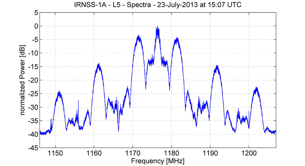
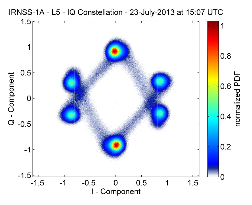
Figure 1 shows the spectrum of the received signal. Centered at 1176.45 MHz, the signal has a single symmetrical main lobe and a number of side lobes characteristic of a spread-spectrum signal. The corresponding IQ constellation diagram is shown in Figure 2. The signal structure appears to be unlike those used by the GPS, GLONASS, Galileo, or BeiDou constellations. Further analysis will be required to sleuth the signal details as ISRO, so far, has not publicly released an IRNSS interface control document (ICD). ICDs characteristically describe a satellite system’s signal structure in detail.
The German scientists caution that “this is a very early snapshot of the current signal transmission and probably both the signal power and the signal quality will change and possibly improve during the in-orbit-testing phase of the satellite’s operation.”


Crazy Motts
good to know about IRNSS. I did a simulation-based analysis of IRNSS and IRNSS-1A to look into the orbital characteristics, related opportunities and challenges that IRNSS may face:
Here’s my analysis of IRNSS:
http://crazymotts.blogspot.in/2013/08/irnss-analysis-of-opportunities-and.html
There are many regional and global navigation satellite systems under implementation and very soon all countries will have access to at least one such system.
Here are my analysis of GNSS applications in commercial aviation industry and the possible business opportunities it may open up:
http://crazymotts.blogspot.in/2013/09/gnss-in-commercial-aviation-impacts.html